CO₂ Measurement

Point-source measurement methods for steam generators and cogeneration facilities.

Overview

This project focused on developing CO₂ measurement methods for once-through steam generators and cogeneration plants. A novel point-source sampling system and methodology were developed to minimize the influence of wind on the measurements. Results obtained with this method closely matched the analytical estimates used to calculate CO₂ emissions from steam generators.

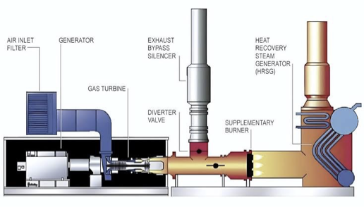
Diagram of a cogeneration system with a gas turbine, supplemental burner, and heat-recovery steam generator
Example cogeneration system showing the gas turbine, exhaust path, supplemental burner, and heat-recovery steam generator.

Measurement Framework

  1. Position a steel-encased sampling probe inside the stack, downstream of the burner, to collect flue gas from a location protected from wind effects.
  2. Draw the flue-gas sample through a cooling coil submerged in a water bath to reduce its temperature and protect the sampling equipment.
  3. Collect the cooled gas in sample tubes and analyze its composition using gas chromatography.
  4. Calculate the measured CO₂ emission rate and compare it with the analytical estimate to evaluate agreement and system performance.

Sampling Location and Flow Control

The sampling point was placed within the stack system downstream of combustion. The protected location and controlled sampling path reduced the influence of ambient wind and helped produce a representative flue-gas sample.
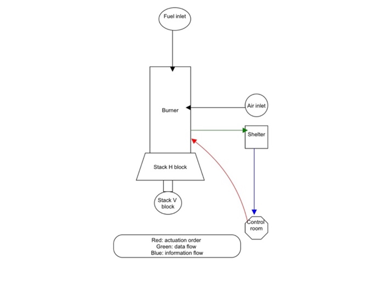
Top-view process diagram showing the burner, air inlet, stack blocks, shelter, and control room
Conceptual process and control layout for the burner, air supply, stack, shelter, and control room.
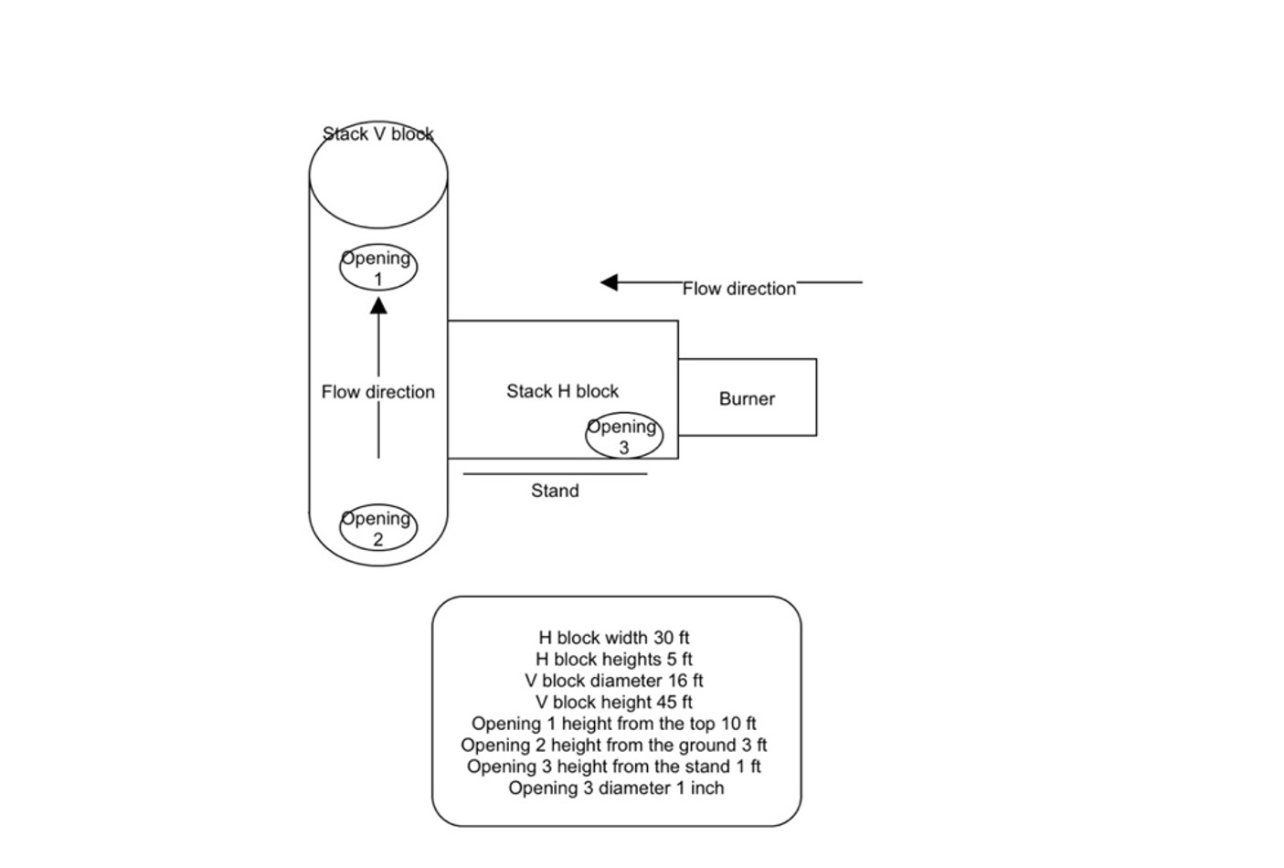
Side-view diagram showing the burner, horizontal stack block, vertical stack block, openings, dimensions, and flow direction
Sampling geometry and flow direction through the horizontal and vertical sections of the stack.

Sample Cooling and Handling

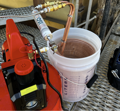
Hot flue gas was routed through a metal cooling coil submerged in a water bath before collection. Lowering the sample temperature protected the tubing and downstream equipment while preparing the gas for analysis.
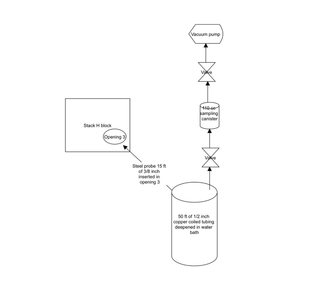
Sampling pipeline from the steel probe through a water-bath cooling coil, valves, sampling canister, and vacuum pump
The sampling pipeline draws flue gas from the steel probe through the water-bath cooling coil and sampling canister using a vacuum pump.
Field sampling equipment with a metal cooling coil submerged in a water bath
The field sampling system uses a submerged cooling coil to lower the flue-gas temperature before collection.

Analysis and Validation

The collected samples were analyzed by gas chromatography. The resulting CO₂ emission rate was then compared with the value calculated using the analytical method. The close agreement between the measured and calculated results supported the performance of the sampling methodology.
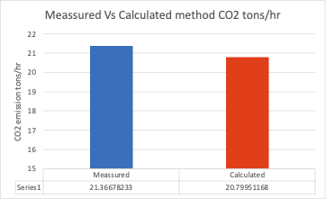
Bar chart comparing measured and calculated carbon dioxide emission rates in tons per hour
The measured CO₂ emission rate closely agrees with the value obtained from the analytical calculation.
SourcesOnce-through steam generators and cogeneration plants
PollutantCarbon dioxide
SamplingProtected point-source flue-gas collection
AnalysisGas chromatography and analytical comparison
StatusMethod development and validation